ESP32 SERVO CLOCK

⏰ Servo Clock Using ESP32 and NTP
This project implements a digital clock using ESP32, multiple servo motors, and a 7-segment display structure. It fetches the current time over WiFi using an NTP server and updates the servo-driven segments in real-time.
✨ Features
⏱ Displays current time (hours and minutes) on servo-driven 7-segment digits.
🌐 Real-time synchronization using NTP server.
🕰 Works in different time zones (default: IST, UTC+5:30).
⚙️ Supports calibration for precise segment positions.
🔧 Modular design for Hour Tens, Hour Units, Minute Tens, Minute Units.
🛠 Hardware Requirements
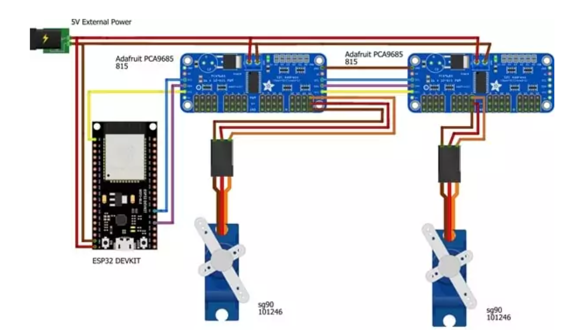
ESP32 Dev Board
8 Servo Motors (for 4 digits × 7 segments)
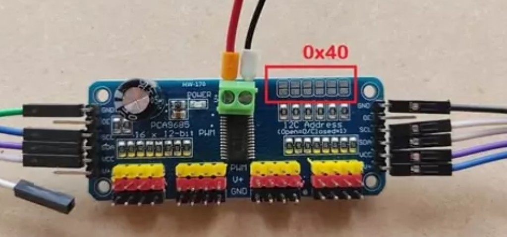
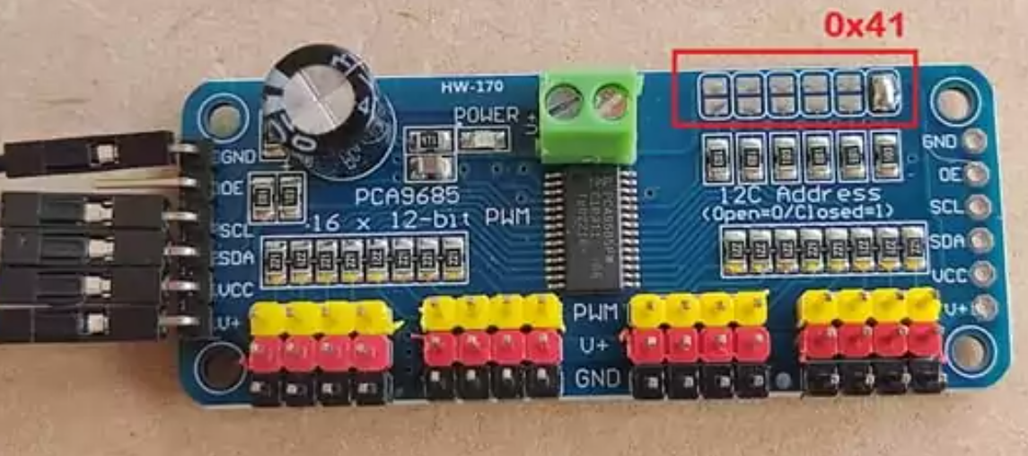
I2C PWM servo drivers (2 × PCA9685)
Jumper wires and power supply for servos
Optional: breadboard or custom PCB for connections
💻 Software Requirements
Arduino IDE or compatible editor
Libraries:
WiFi.h (ESP32 core)
time.h
Wire.h
SevenSegment library for servo-driven digits
Access to WiFi network for NTP synchronization
⚡ Setup Instructions
Connect the hardware:
ESP32 SDA → Servo driver SDA
ESP32 SCL → Servo driver SCL
Servo motors connected to PWM channels of PCA9685 boards.
Configure WiFi and timezone:
Set ssid and password for your WiFi network.
Set TimeZone as per your region.
🟢 Calibration (Mandatory First Step)
⚠️ Highlighted Step:
Before running the clock normally, uncomment the CalibrateServos(); line in setup().
Upload the code to the ESP32.
The servos will move all segments to 88:88 – this allows you to physically adjust and fine-tune each segment.
After calibration, comment out CalibrateServos(); again, then upload the code again to start the real-time clock. ✅
Run the clock:
After calibration, the code fetches time from the NTP server and updates each servo to reflect the current hour and minute. ⏰
🧩 How It Works
Time Sync: The ESP32 connects to your WiFi and requests the current time from pool.ntp.org. 🌐
Time Conversion: Hour and minute values are split into tens and units. 🔢
Servo Update: Each segment of the 7-segment display is controlled by a servo, which moves to its ON/OFF position according to the number to display. 🎯
Looping: The clock checks the time every 250ms and updates servos only when minutes change, reducing unnecessary servo movement. 🔄
⚠️ Notes
Servos should have sufficient power to avoid jitter. 🔋
Ensure the calibration step is done before running the clock normally – this is essential for proper functioning. 🛠
Timezone can be adjusted by modifying the TimeZone variable. 🌍
🛠 Troubleshooting
Servos not moving: Check connections and PCA9685 addresses. ❌
WiFi not connecting: Confirm SSID/password and WiFi strength. 📶
Incorrect time: Ensure NTP server is reachable and timezone is set correctly. ⏳
📚 References
NTP Protocol Documentation 🌐
ESP32 WiFi and Time Libraries 💻
PCA9685 Servo Driver Datasheet ⚙️
Category
Hardware+Software
Difficulty
Intermediate
- ✓ Complete Source Code
- ✓ Project Report (Word/PDF)
- ✓ PPT Presentation
- ✓ Installation Support
Building block
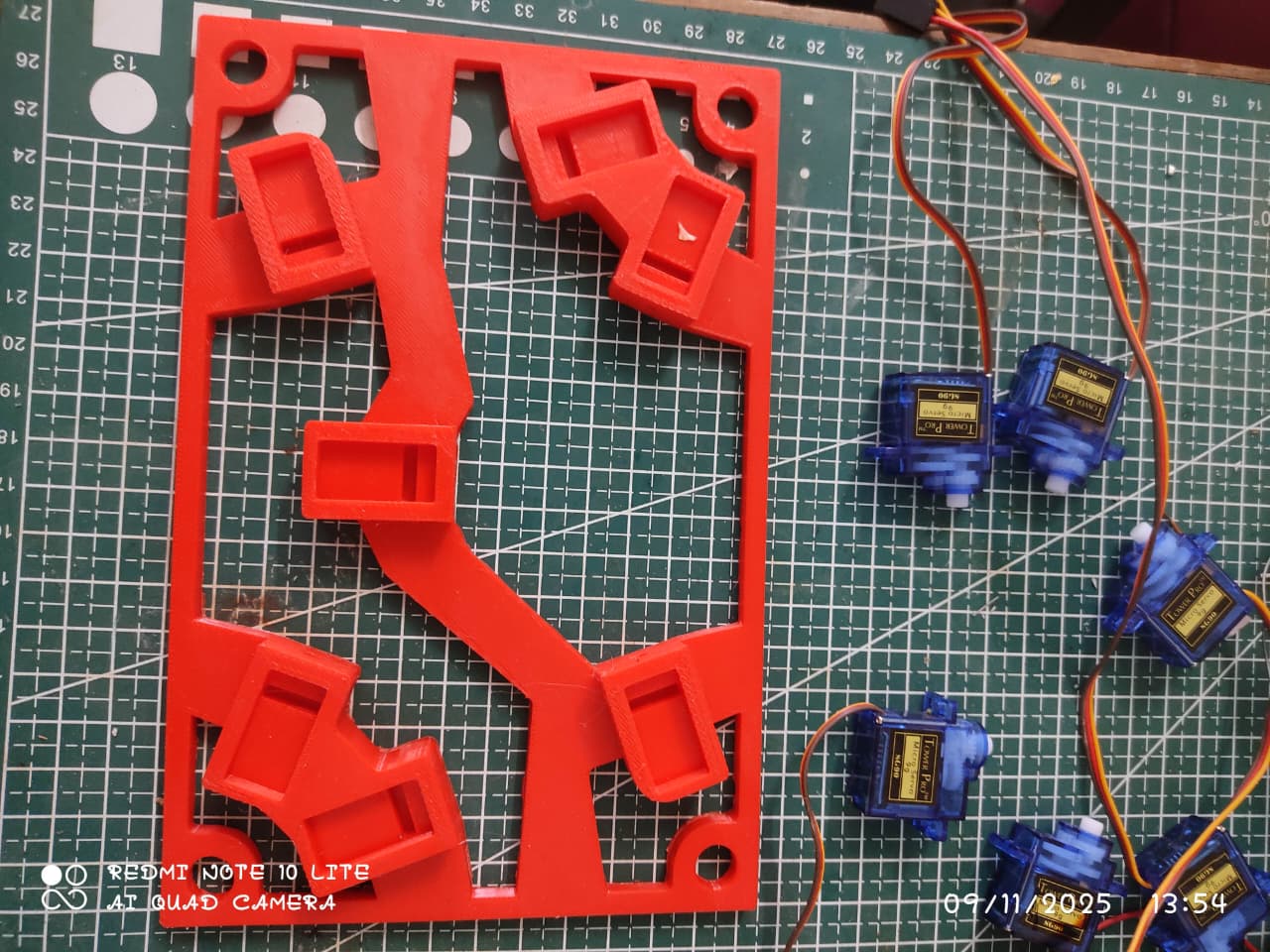
After 3d stn file got printed put the servo motors for all 4 blocks like shown in the image
Attach the Wings
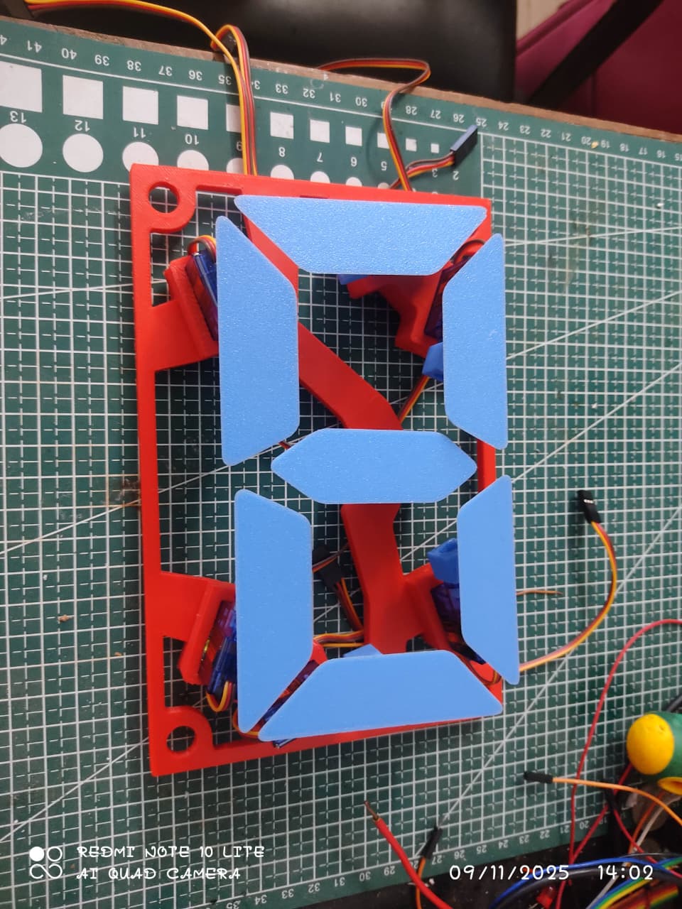
in this part we will attach the 3 d printed custom wings for 7 segment like structure
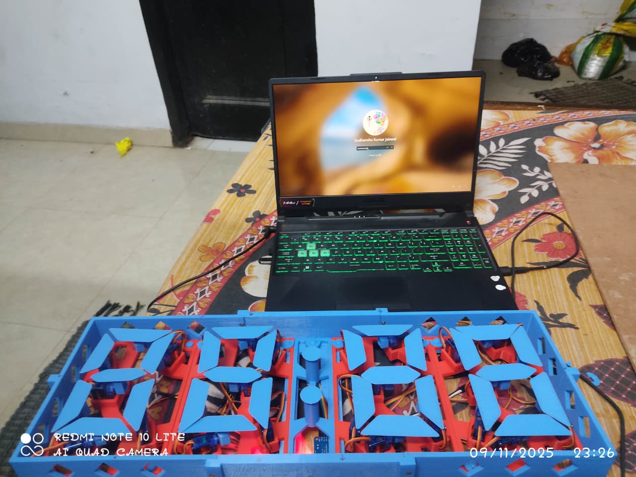
Adding 4 blocks
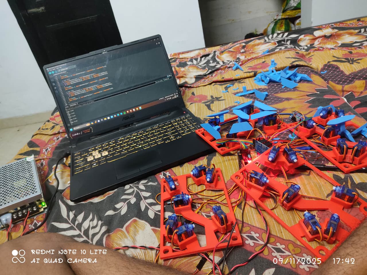
Put all the blocks on the enclosure
Servo HH connection
Do the wiring for HH block as shown in the pic below
Servo MM connection
Overall Connection
Arduino IDE Code
/***********************************************************************
 *  Servo-Motor Clock Using ESP32
 *
 *  Description:
 *  This Arduino sketch controls a servo-based 7-segment clock using an ESP32.
 *  It fetches the current time from an NTP server over WiFi and updates
 *  servo-driven digits to display the hours and minutes in real-time.
 *
 *  Features:
 *    - Real-time clock using NTP synchronization
 *    - 7-segment digits driven by servo motors
 *    - Supports calibration for precise servo positioning
 *    - Works with different time zones (default: IST, UTC+5:30)
 *
 *  Hardware Requirements:
 *    - ESP32 Development Board
 *    - 8 Servo Motors (for 4 digits × 7 segments)
 *    - 2 × PCA9685 I2C Servo Drivers
 *    - Jumper wires and appropriate power supply
 *
 *  Note:
 *    Before running normally, perform calibration by uncommenting
 *    the CalibrateServos() function in setup() and uploading the sketch.
 *    The servos will move to 88:88 to allow adjustment. After calibration,
 *    comment it back and upload the sketch to start the clock.
 *
 *  Author: Siddhu(Sudhanshu Kumar Jaiswal)
 *  Date: 2025-11-12
 ***********************************************************************/

#include <WiFi.h>
#include <time.h>
#include "SevenSegment.h"

const char *ssid = "Siddhu";       // Name of the Wifi Network
const char *password = "12345671"; // Password of the Wifi Network

const char *ntpServer = "pool.ntp.org";  // URL of NTP Server
const char *TimeZone = "IST-5:30";       // India Standard Time (UTC+5:30)

// const char *TimeZone = "PST8PDT,M3.2.0,M11.1.0"; // America/Los_Angeles Time ZOne

#define SDA_PIN 21
#define SCL_PIN 22

// Hour digits
SevenSegment HourTens = SevenSegment(0x40, 7);  // Create an object of Hour Tens driver
SevenSegment HourUnits = SevenSegment(0x40, 0); // Create an object of Hour Units driver

// Minute digits
SevenSegment MinuteTens = SevenSegment(0x41, 7);  // Create an object of Minute Tens driver
SevenSegment MinuteUnits = SevenSegment(0x41, 0); // Create an object of Minute Units driver

// Segments On/Off servo pos                   1    2    3    4    5    6   7
const uint16_t HourTensOnPos[SEGMENT_NUMS] = {368, 368, 368, 368, 368, 368, 368};
const uint16_t HourTensOffPos[SEGMENT_NUMS] = {565, 172, 565, 565, 172, 565, 172};

const uint16_t HourUnitsOnPos[SEGMENT_NUMS] = {368, 368, 368, 368, 368, 368, 368};
const uint16_t HourUnitsOffPos[SEGMENT_NUMS] = {565, 172, 565, 565, 172, 565, 172};

const uint16_t MinuteTensOnPos[SEGMENT_NUMS] = {368, 368, 368, 368, 368, 368, 368};
const uint16_t MinuteTensOffPos[SEGMENT_NUMS] = {565, 172, 565, 565, 172, 565, 172};

const uint16_t MinuteUnitsOnPos[SEGMENT_NUMS] = {368, 368, 368, 368, 368, 368, 368};
const uint16_t MinuteUnitsOffPos[SEGMENT_NUMS] = {565, 172, 565, 565, 172, 565, 172};

void setup()
{
  // Start Serial for debugging
  Serial.begin(115200);


//                                         THIS IS THE VERY MAIN THING TO DO SO FOCUS ON THIS LINE


// Put all the servos ON , 88:88 and wait for ever .Only for Test/Calibration
 // CalibrateServos();

  // Start Clock application
  InitClock();
}

void loop()
{

  static struct tm prevTimeInfo = {0};

  // Get current time
  struct tm TimeInfo = getCurrentTime();

  // compare minutes , if change then refresh
  if (prevTimeInfo.tm_min != TimeInfo.tm_min)
  {
    prevTimeInfo = TimeInfo;

    // Print Current Time and Date
    Serial.println(&TimeInfo, "%A, %B %d %Y %H:%M:%S");

    // Convert Hour and minutes in Digits
    int Hora = TimeInfo.tm_hour;
    int Mim = TimeInfo.tm_min;

    int hourTens = Hora / 10;
    int hourUnits = Hora % 10;
    int minuteTens = Mim / 10;
    int minuteUnits = Mim % 10;

    // Refresh every servo digit according to the time
    HourTens.setNum(hourTens);
    HourUnits.setNum(hourUnits);
    MinuteTens.setNum(minuteTens);
    MinuteUnits.setNum(minuteUnits);
  }

  // Wait a little  , we don't need to go that fast
  delay(250);
}

// Initialize all servos   , I2C pins and Drivers
void InitServos(void)
{
  Wire.begin(SDA_PIN, SCL_PIN);

  if (!HourTens.begin(HourTensOnPos, HourTensOffPos))
    Serial.println("HourTens not connected!");
  if (!HourUnits.begin(HourUnitsOnPos, HourUnitsOffPos))
    Serial.println("HourUnits not connected!");

  if (!MinuteTens.begin(MinuteTensOnPos, MinuteTensOffPos))
    Serial.println("MinuteTens not connected!");
  if (!MinuteUnits.begin(MinuteUnitsOnPos, MinuteUnitsOffPos))
    Serial.println("MinuteUnits not connected!");
}

// Initialize Clock connecting to Internet and initializing Time and Servos
void InitClock(void)
{

  WiFi.begin(ssid, password);
  // Espera a que se establezca la conexión
  Serial.println("Connecting to Wifi");
  while (WiFi.status() != WL_CONNECTED)
  {
    delay(1000);
    Serial.println(".");
  }

  Serial.println("Connected!");

  initTime(TimeZone);

  InitServos();
}

// Initialize all the servers , by default they always start ON 88:88
void CalibrateServos(void)
{
  InitServos();
  delay(5000);

  // Wait for ever , so the user can adjust the segment position
  while (1)
  {
     for (size_t i = 0; i < 99; i++)
    // {
    //   // Convert Hour and minutes in Digits
    //   int Hora = i;
    //   int Mim = i;

    //   int hourTens = Hora / 10;
    //   int hourUnits = Hora % 10;
    //   int minuteTens = Mim / 10;
    //   int minuteUnits = Mim % 10;

    //   // Refresh every servo digit according to the time
    //   HourTens.setNum(hourTens);
    //   HourUnits.setNum(hourUnits);
    //   MinuteTens.setNum(minuteTens);
    //   MinuteUnits.setNum(minuteUnits);
    delay(1000);
  }

  // MinuteUnits.setEmpty();
  // MinuteTens.setEmpty();
  // HourTens.setEmpty();
  // HourUnits.setEmpty();
  // delay(1000);
  // MinuteUnits.setFull();
  // MinuteTens.setFull();
  // HourTens.setFull();
  // HourUnits.setFull();
  // delay(1000);
}

// Initialize time by starting NTP synchronization , wait till get a valid time and set Time Zone
void initTime(String tz)
{
  struct tm TimeInfo;

  Serial.println("Setting up time");
  configTime(0, 0, ntpServer); // First connect to NTP server, with 0 TZ offset
  while (!getLocalTime(&TimeInfo))
  {
    delay(1000);
    Serial.println(".");
  }
  Serial.println("  Got the time from NTP");

  // Now we can set the real timezone
  Serial.printf("  Setting Timezone to %s\n", tz.c_str());
  setenv("TZ", tz.c_str(), 1); //  Now adjust the TZ.  Clock settings are adjusted to show the new local time
  tzset();
}

// Get current time from internal ESP32 RTC
struct tm getCurrentTime(void)
{
  struct tm TimeInfo;
  if (!getLocalTime(&TimeInfo))
  {
    Serial.println("Invalid Time");
  }
  return TimeInfo;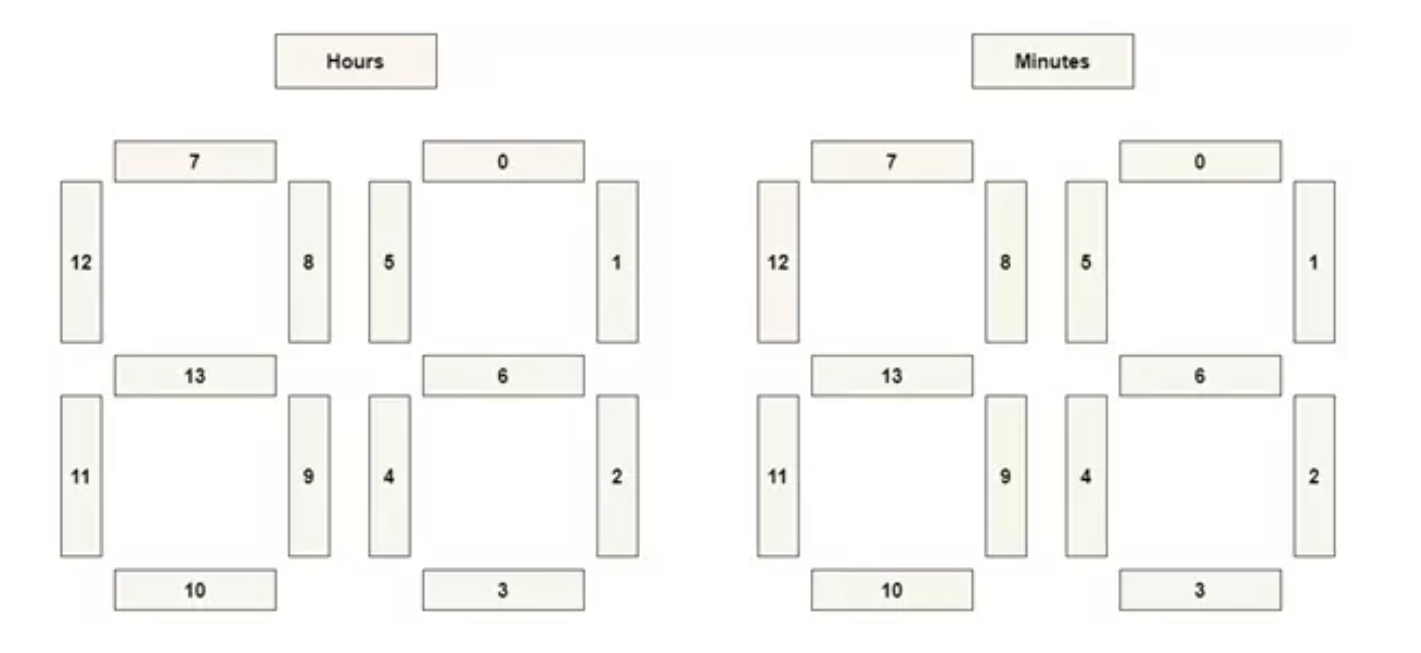
}All Segment connection for each 7 segment display